All posts relating to Maxwell Render 1.x
User avatar
By Tim Ellis
#187801
Thomas An. wrote:It is true for all glass objects, no matter how thick or thin (solid or hollow)... the attenuation is a constant regardless of thickness.
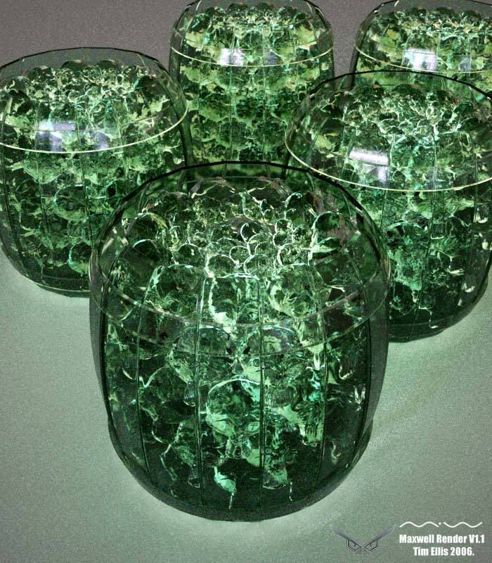
lol, we've been here before my good friend. ;) http://www.maxwellrender.com/forum/view ... ion#163461

Tim.
User avatar
By Thomas An.
#187804
...Attenuation is based on the size of the object ...
Yes Tim,

That advice above was *not* accurate. Back then it was still early and even expert users were grappling with it sometimes.
Last edited by Thomas An. on Thu Oct 05, 2006 3:05 am, edited 1 time in total.
User avatar
By Tim Ellis
#187806
Cool, I'm set to try your suggestions anyway, as the first were correct for the mesh size.

Will post new version tomorrow if possible.


Many thanks,

Tim.
User avatar
By b-kandor
#187813
Thomas An. wrote:It is true for all glass objects, no matter how thick or thin (solid or hollow)... the attenuation is a constant regardless of thickness.
This is an amazingly useful bit of understanding - I can officially stop second guessing this setting.

Thank you very much! I've been basing this setting on the bounding box of my object all along :oops:
User avatar
By Tim Ellis
#188030
Thomas I did some tests today, using your suggestions.

I ran three, single monkey head renders for 30mins each, with just a material change in each one.

The difference between the glass mxm I used and your settings, gave a 0.01 increase to the benchmark number and sample level number for your setting.

Changing the attenuation on the mxm I used from 40cm to 3cm also increased the BM and SL numbers by 0.01.

So while it does optimize the glass, it's by a tiny ammount.

I have since tried dropping the ND number to 1.11, which has optimized it to a 65 benchmark and SL 8 in 3minutes. I've also activated dispersion which I hadn't before and there are now many more caustics present.

This new version is renderiong overnight and I'll post over the weekend.

Tim.
User avatar
By Thomas An.
#188033
I used and your settings, gave a 0.01 increase to the benchmark
Hi Tim,

When I said "optimized" I meant in terms of proper settings for physical correctness ... not "optimized" in terms of speed. Sorry for the confusion.
User avatar
By Tim Ellis
#188035
Thomas An. wrote:
I used and your settings, gave a 0.01 increase to the benchmark
Hi Tim,

When I said "optimized" I meant in terms of proper settings for physical correctness ... not "optimized" in terms of speed. Sorry for the confusion.
I thought you might have, my fault really. :oops:

Had I used the high grade glass preset instead of the common glass preset, I presume that the values would have been the same as your settings. It just seems strange that Maxwell would give me a material which isn't physically correct, but this might explain it. I've not got Maxwell here at work, so I can't check.

Cheers,

Tim.
User avatar
By Eric Lagman
#188037
I had no idea on this either. I was taking Mverta's old advice of setting the attenuation to twice the thickness of my object or there about. I was always fighting with how saturated my transmittance color was and the attenuation value. This sounds like it will make things much easier and give me the most realistic results. I will have to give it a try. Cant wait.
User avatar
By Thomas An.
#188038
Tim Ellis wrote:Had I used the high grade glass preset instead of the common glass preset, I presume that the values would have been the same as your settings.
It is not really your fault, if this is what the wizard is doing for you.
I feel that the Maxwell presets still need some tweaking. Right now they allow for some user flexibility ... enabling the user to set the transmittance color in a way that goes against your ND value. I could go into it with more detail but it gets technical.

Basically when the wizard comes up and asks you for a color then use HSV (instead of RGB). Chose your hue and then I would go here: http://www.maxwellrender.com/forum/view ... hp?t=17142 to the bottom of that cheat-sheet and pick a 'v' value corresponding to the Nd.

Once you set it up this way the wizard will create a reflectance color for you (which is a complementary hue) ... but it doesn't make sure that 'v' value of the the reflectance color adds to 255 with the transmittance 'v' value (you have to ensure it manually).

Of course the above technique is for realistic glass ... now if you aim for other types of dielectrics (like plastics and other resins) then other settings might be more suitable.
User avatar
By Tim Ellis
#188039
Thank you very much for your help and great information Thomas. :D

Tim.
User avatar
By ivox3
#188040
Monkey Business would be a better post title. Okay, ...there's my 'monkeys out of control' thread contribution.

Nice work Tim .... a bit fascinating this monkey thing. :)
User avatar
By Dexel
#188041
...Attenuation is based on the size of the object ...

That advice above was *not* accurate. Back then it was still early and even expert users were grappling with it sometimes.
I guess mverta's advice concerned the desired result (of distinguishable varying saturation across the object) and not accurate physics.
Of course there is a relation between object size and attenuation distance - when the desired look is your "constant". Kooky math, right. But true..
User avatar
By Tim Ellis
#188286
Cheers ivox. :D

:arrow: Dispersion activated:-
Image

Tim.
User avatar
By b-kandor
#188289
The monkeys are looking cool. But what is causing the black edges on the barrel tops, this is exactly what I see with glass in maxwell when I'm trying to render glass tables or shelves. Very dark edges that look very unrealistic to me. The glass I see in real life is much more transparent on the edge. This is maybe related to the 3.01cm attenuation value?

It's this dark edge that has always made me think I needed a greater attenuation value.... now I still feel confused?

Kandor
User avatar
By Thomas An.
#188291
b-kandor wrote:The monkeys are looking cool. But what is causing the black edges on the barrel tops, this is exactly what I see with glass in maxwell when I'm trying to render glass tables or shelves. Very dark edges that look very unrealistic to me. The glass I see in real life is much more transparent on the edge. This is maybe related to the 3.01cm attenuation value?

It's this dark edge that has always made me think I needed a greater attenuation value.... now I still feel confused?

Kandor
Well, the 3cm attenuation has been confirmed both analytically and with a photo test. Of course common glass may not always be exactly at 3.00cm there can be a range (depending on quality) say +/-2cm for common glass. Now if we go to fiber-optics grade materials then yeah the attenuation can go high.

Common glass 3cm attenuation photo-test.
Image

Image

In Tim's image the glass does look kinda weird ... but I would first look at scale issues and double-check the transmittance color first.
Help with swimming pool water

I think you posted a while back that its best to u[…]

Sketchup 2026 Released

Considering how long a version for Sketchup 2025 t[…]

Greetings, One of my users with Sketchup 2025 (25[…]

Maxwell Rhino 5.2.6.8 plugin with macOS Tahoe 26

Good morning everyone, I’d like to know if t[…]