#278508
Hi again everyone: I am having a strange issue (strange to me at least). I am lighting a model using an .mxi texture of a lightbox- just an image I made in Gimp of a diffused white ellipse, and 3 emitters.

The problem is that I have a very dark area that seems to follow my camera around. In the first image you will see a very dark area at the bottom of my shot.

Image

So I zoomed my view out to see if I could diagnose the problem- I have moved lights around, base platform around and still no matter what I always have the dark area at the bottom of my shot.

Image

I thought that I could just zoom in on my model a little and I would avoid this dark spot but to no avail it just turns out as in the first pic.

I then thought that the dark spot was a shadow from the 3 spherical emitters that I have over top of my scene so I made them into transparent emitters so they wouldn't cast a shadow. Again with the same results. Here is a shot of my set up

Image

And here is a rendered view of my lighting set up from the outside of my scene.

Image

Any of you folks have any idea where I am going wrong. Thanks as usual!!!
Cary
By JDHill
#278511
Can you upload, or post the details of, the floor material? Also, I can't really tell from the screenshot - what do those emitters look like?
User avatar
By caryjames
#278515
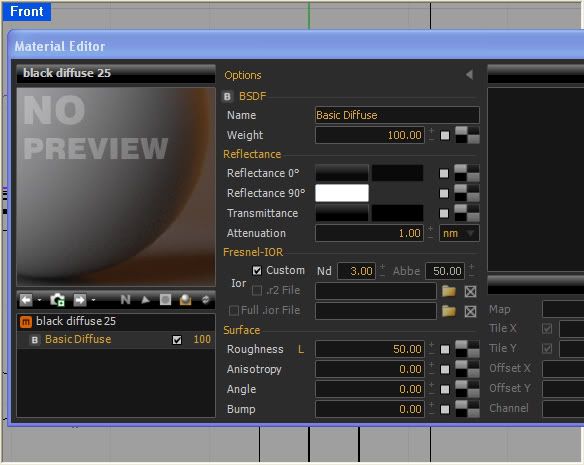
Hi JD: The floor is a simple diffused that I made with the wizard, the only thing changed was the roughness-- here is a screen shot.

Image

The additional emitters are three half spheres as shown here.

Image

But I get the same results with and without those spherical emitters.

I was wondering if the camera ever casts a shadow?
Thanks
By JDHill
#278527
No, the camera cannot cast any shadow. The dark spot is most likely due to the floor material - do you have any particular real-world material that this is supposed to correspond to? What you are seeing is the fresnel curve from your black (or nearly so) Reflectance 0° color to your white (or nearly so) Reflectance 90° color on a 50% rough bsdf with Nd=3.0. Those are the parameters which are coming together to show you closer to the black frontal color at the place on the floor where the line-of-sight is nearly perpendicular. Try doing this:

In the existing BSDF:

- change Weight to 60
- change Roughness to 99

Then, add another BSDF:

- set Weight to 40
- set Reflectance 0° to 130, 130, 130
- set Roughness to 50

This will make the black color quit responding to view-angle, due to the high roughness. Then, the reflectivity you were after by setting roughness to 50 is handled on its' own in the second BSDF, which is used only for reflection and is not meant to contribute to the actual color of the material. This material is almost identical to what you would get if you used the plugin's Wizard to create a black, 50% rough plastic.

About your emitters - these are probably adding alot of time to your renders. Try constructing them out of single rectangles, or if that shows up bad in your reflections, as octagonal-ish discs. Personally, I would construct these directly as meshes using a closed polygon polyline and Mesh > From Closed Polyline, or by creating a mesh cylinder and extracting the faces of one end into a mesh disc.
User avatar
By caryjames
#278528
Thanks JD: That makes sense now- I would have expected that the colour would get more black closer to the camera but I would have thought it would have been straight across parallel to the bottom of the screen. Once I thought about it for a minute with that end understanding it makes sense now that it wouldn't.

I knew better than to use other than flat planes for my emitters and to be honest am not sure what I was thinking :).

I will try the settings that you suggested- I will have to put my thinking hat on to try and figure out how you came up with that solution.... one thing at a time I guess :).
Thanks again
Cary
User avatar
By caryjames
#278545
Thanks JD: I tried that and it solved my problem!!!

I know that I am asking a lot but do you think that you could you take some more time out and explain your solution to me :)? How did you know that adding another BSDF layer in that way would make the black colour quit responding to view-angle?

I am just getting into adjusting materials and am fascinated by these properties.

Thanks again!
Cary
By JDHill
#278582
It is not really complicated - with an understanding of how reflectance 0, 90, and Nd interact with one another. I'll try to simplify this:

Reflectance 0°: the reflectivity of parts of an object which are perpendicular to the camera
Reflectance 90°: the reflectivity of parts of an object which are parallel to the camera
Nd: defines the curve between Reflectance 0° and 90°

Basically, low Nd values cause the 0° color to dominate the 0-90° curve, and vice-versa for high ones. Visually speaking, picture a red laminate table-top; if you placed a camera above the table facing down, it would see mostly the red material. If you set the camera directly on the table, facing a window, you would no longer see the red color - this material would (for the most part) reflect the environment. If you were to take a movie from this camera as you rotated it from the first position (above, looking down) to the second (sitting on the table), you would observe a certain curve where the predominantly-red color would gradually fade into total reflection; this is the curve I am talking about which is represented in the Nd parameter.

In your original example, the Nd is relatively high and the roughness medium - this particular combination was coming together such that through the angle visible in your camera (from the bottom of the frame to the top) we are able to see the Nd curve in action. The result did not seem to be what you were looking for, so it is most logical to work from here by separating out the two objectives you want to acheive: color and reflectivity. As I proposed, I would do this by using two layers which can be controlled independently - one concerned only with color, and the other only with reflectivity.

For a more detailed and technical description of these things, I would recommend to read the Maxwell manual (not the plugin manual) starting around page 44.

Cheers...
User avatar
By caryjames
#278590
Thanks again JD: That really helps clarify things at least to me :). I have read that section of the manual over and over and understand the general gist of things but putting that into practice at least for me is sometimes difficult.

Often I find that because of all the variables that go into a render (lighting, models, textures, materials) it is difficult to problem solve an issue. I start trying to solve a certain issue and end up boggled with so many parameters to deal with.

I still wish that there were specific tutorials where Next Limit walked you through changing material settings and explained what was going on and why. I am learning day by day but it is a bit slow :)
Cary
User avatar
By caryjames
#278601
Not in a long time... and when I did I couldn't see what on Earth was going on because of the small size of the images. I will take a look on my new monitor and see if I can learn something :)
Sketchup 2025 Released

Thank you Fernando!!!!!!!!!!!!!!!!!!!!!!!!!!! hwol[…]

I've noticed that "export all" creates l[…]

hmmm can you elaborate a bit about the the use of […]

render engines and Maxwell

Funny, I think, that when I check CG sites they ar[…]