#379052
Hi,
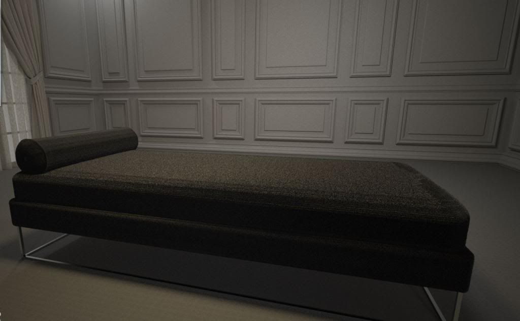
I think I've read everything there is to read online about how to get materials with displacement layers to behave properly in Maxwell Studio and have had very little success with them. I've run tons of tests and have worked with all of the variables such as subdivision, height of the displacement, the UV layer and even importing meshes with different densities into Maxwell studio..workflow is modelling in Rhino and importing as obj into studio. I really want to figure this out, can someone help??
#379074
wiredupbook wrote:Hi,
workflow is modelling in Rhino and importing as obj into studio.
you should mesh your nurbs inside rhino, and inspect them before export as obj. maybe you are already doing so.
the mesh settings are very important for displacement to work good & efficiently.

http://wiki.mcneel.com/rhino/meshfaqdetails
#379117
Image

Here's a recent example. look at the edges of the daybed, there are strange lines and triangles that are affecting the texture. This is the main issue I'm having and I'm fairly sure that it has something to do with the way I'm meshing the objects.
Any tips or knowledge would be appreciated
By Polyxo
#379122
Likely that this is not what you want to hear but I would suggest rebuilding the relevant bits inside a mesh modeller.
The reason is that displacement mapping requires proper = unwrapped UV's and good polygon-flow. A Nurbs polysurface
with filleted edges is no suitable input and can not get prepared in a suitable way inside Rhino or Nurbs modellers in general.

These parts would take just a few minutes to model inside any subdivision app and gave far better input for what you want to do.
It was also easy to introduce some subtle randomness into the upholstery. Alternatively you could optimize your Nurbs rendermeshes
and unwrap inside these inside a third party app but it's hardly worth it as the geometry is so simple to recreate.

That said... . you should come along with a Normal map in this case unless you plan radical closeup shots.
By Polyxo
#379132
wiredupbook wrote:So basically use Maya instead of Rhino??
You could use any mesh modeller which lets you unwrap stuff. Also free Blender was an excellent option.
One could import the existing upholstery from Rhino for size reference and quickly redo these items, based on mesh primitives.

This statement was meant for applying displacement though. On second thought I'd rather advise to work with a normal-map
in this particular example. It should work fine for simulating roughness and frizz of woven cloth from this distance. While also
here it was better to have unrolled geometry, the normal-map doesn't actually deform the underlying volumes and therefor
behaves somewhat more forgiving.

Using a normal-map one will probably come along with box mapping, cylindrical mapping or custom mapping (using a similarly
shaped single surface as a UV-template) inside Rhino.
User avatar
By Mihai
#379143
One workflow would be:

-export a pretty dense obj mesh from RHino. The important thing when meshing is to avoid long elongated triangles. This is mentioned in the displacement docs:
Objects made of evenly distributed polygons are preferable because they provide better quality. You should avoid base geometry with disproportionate triangles that converge to the same point. In areas with many small, converging triangles you may get artifacts when using displacement. This geometry is usually found in polygonal objects tesselated from NURBS geometry used in CAD applications. It is recommended that you introduce more iso-lines in the initial NURBS geometry in these areas to create more evenly-sized polygons. Some CAD applications allow good control over the tesselation, offering the creation of quads instead of triangles, or a limit to how long a triangle can be in the conversion.
-one of the best UV unwrappers out there is called Unfold3D (http://www.polygonal-design.fr/). Granted its an extra investment but it works great even on very chaotic type meshes that nurbs modellers produce and the time it saves you, plus the quality of the unwrapping makes it a great investment in my opinion - especially if you model mainly in a nurbs package. So, import the obj into Unfold3D, unwrap it, then export the obj again with proper UVs.

- import the nice UVd obj into Studio.

This procedure may seem tedious but you really don't have much choice if you want to use displacement - which acts on the actual underlying geometry itself and needs very good UVs to avoid artifacts, plus a decent mesh without too many long sharp triangles but instead more evenly subdivided ones.
#379149
great advice all around. Thank you!

I am very beginner level at Maya right now so improving my workflow in Rhino is preferable for the short term.
I just need to now figure out how to eliminate the triangles in my Rhino mesh..
By Polyxo
#379165
wiredupbook wrote:great advice all around. Thank you!

I am very beginner level at Maya right now so improving my workflow in Rhino is preferable for the short term.
I just need to now figure out how to eliminate the triangles in my Rhino mesh..
As soon as there's trimmed surfaces inside a Nurbs model you will inevitably have triangles around surface seams.
This isn't Rhino specific but happens in all CAD-applications. Its possible to minimize their size and they normally
have no negative impact on the shading. Rhino's mesher actually is one of the best implementations found inside
Nurbs apps, results largely depend on understanding its numerous parameters. Unfortunately one can't give general
advice – appropriate settings totally depend on the model topology but also on its physical size.
Last edited by Polyxo on Wed Mar 26, 2014 7:59 pm, edited 1 time in total.
By Polyxo
#379166
-one of the best UV unwrappers out there is called Unfold3D (http://www.polygonal-design.fr/). Granted its an extra investment but it works great even on very chaotic type meshes that nurbs modellers produce and the time it saves you, plus the quality of the unwrapping makes it a great investment in my opinion - especially if you model mainly in a nurbs package. So, import the obj into Unfold3D, unwrap it, then export the obj again with proper UVs.
I come to another conclusion. After testing about every UV-mapper in the market over the years I think it's safe to say that a UV-Unwrapper
which works "great" with Nurbs polysurfaces doesn't exist. Great is supposed to say "about as good or as good as with low res subd-cages", no?
Hands down, No.
I find, that those tools and all their functionalities are 100% optimized towards Subd-Mesh input, UV-Unfold is no exception. It's shortest path selector
works nicely on low poly cages, yes. But on Nurbs meshes? Yeah, a bit better than apps which don't have such, but it doesn't allow for fast and controlled
editing along triangulated surface seams – in my book certainly not at all worth minimum 300 Euro for a single license – that is for that particular use-case.

The best options I could find for editing meshes exported from CAD are 3DCoat (featuring a shortest path implementation which performs way
nicer on surface seams than Unfold3D) and generally offering tons more interesting features for the same price as UV-Unfold. Also (but
here it gets more expensive) Zbrush's UV-Master can be very helpful in certain scenarios. It within seconds can unroll the craziest meshes as single island
which may be great for procedurals but there's also very interesting options to remesh to AllQuads. The result may then be treated with all methods
which also work with SubD-basemeshes.
- import the nice UVd obj into Studio.This procedure may seem tedious but you really don't have much choice if you want to use displacement -...
Fwiw...that's not necessary, one can also re-import the uv-ed geo to Rhino and build the scene here.
#379169
use max endge length to clamp mesh face size
use max aspect ration to avoid steep triangles.. ýou could even set this to 1 or 2 to get meshes that are as quadratic as possible, good for displacement, but naturally dense, depending on geometry.

jagged seams will eventually skip triangle creation on edges, but not trims.BUT vertices won't line up on polysurface edges

Generally, when you model with nurbs, think SingleSurface as much as possible.

a geometry like the bed could be build like this:

i quickly made this using sweep2 and maintain height option, and then set the edge control points to 0 on Z. it would need some more work, but especially for cloth, nurb simulate the behaviour quite well! compression and relaxation will be represented by the nurbs inherent UVs so you CAN you this to make very realistic models with the right tricks.

units are cm, so when you apply these mesh settings, you get a perfectly quad output for the single surface with the profit of the nice normals produced from nurbs geometry.for displacement of the bed i would go as low as 7-2 mm edge length, so 0.7 - 0.2 in the mesh dialogue box if model is centimeters.


Image
By Polyxo
#379174
Yup, that's an approach which will work in this case.
But isn't it tragic, that one has to cheat with needlessly complex Nurbs geometry in order to yield simple, displace-able mesh geometry?

I mean - that is certainly not how a person who designs a Sofa for manufacturing (and who needs believable pictures nontheless) would model this in CAD.
That's nothing but a cheap Visualizers trick, man :)
#379177
Polyxo wrote: I mean - that is certainly not how a person who designs a Sofa for manufacturing (and who needs believable pictures nontheless) would model this in CAD.
That's nothing but a cheap Visualizers trick, man :)
its a render forum isn't it? :wink:

3min render
Image


thinking in singlesurfaces is just about keeping a lightweight and editable model. if there are discontinuities in the surface, the are most likely breaks in uv space too. in that sense I suggest to model with as few elements as possible.

eg. if you want to represent a sharp corner of a wall, you can also do this by merging(not join) 2,3, etc surfaces along the edge which are degree 1 extrusions into a single surface, and still maintain homogenous uv mapping across the faces. much nicer to texture/edit.

it would be interesting to see the real flat layout of the cuts such a bed is made of; i would guess seams in all the edges or a continuous stripe along the side with a single seam and a second flat piece filling the middle.

these patches can be represented by single loose (untrimmed) surface patches.
the seam is important, and depending on the type of material (eg leather..) visible or more hidden.

by masking the edges to black, displacement can be avoided at the seam, or enhanced to show stitches etc...

the only real problem is mapping uv space back to real scale space. or in other words the masking would be more stretched because of heterogeneous uv spacing between the patches. so you would have to make separate displacement maps for each patch size.
Sketchup 2024 Released

I would like to add my voice to this annual reques[…]