User avatar
By Tim Ellis
#167710
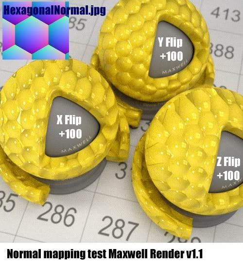
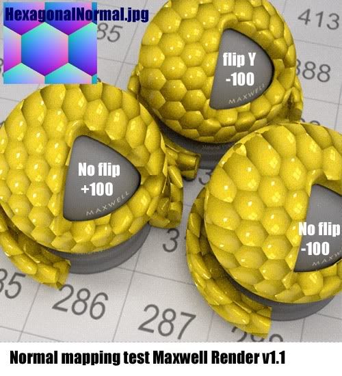
My normal mapping tests with V1.1.

In each case the HexagonalNormal.jpg map was used from the texture folder, with no other maps used, just a base yellow colour. However I did put the Normal map into both bsdf layers and each one matched the other layer for values and flip type.

I think the rest is self explanatory, although I don't understand the flip system and how it's relevant to a certain type of normal map.

I didn't do a negative X or Z flip as they didn't look as convincing as the Y flip version.

Which type of normal map does M~R accept?

Anyway here are my preview window quick renders to check things are okay.


Image

Image


Tim.
User avatar
By tom
#167857
--------------------> X
|
|
|
|
|
|
V

Y

When using data from texture, the above is screen coordinates and origin is at the top-left. However some applications creates map like:

Y

A
|
|
|
|
|
-----------------> X

So, in the code the formula is based on screen coordinates and you should interpret Y as flipped, which is green channel in fact.

Example:
Encoding of a bumpy (outwards) sphere taking care of screen coordinates would look like this.

NORMAL MAP (encoded topleft as origin)
Image

RED
Image

GREEN
Image

See the red channel gradient (0-255) goes from left to right and the green channel gradient goes from up to down. Because the origin is top-left and this kind of normal map will be rendered without flipping any axis by the core.

And for most common packages like C4D, ZBrush etc, the same bumpy (outwards) sphere is encoded like the following:

NORMAL MAP (encoded bottomleft as origin)
Image


RED
Image

GREEN
Image

See now the origin is based on bottom left and so the green gradient is going from down to up. Which means, such maps' Y direction have to be treated invert according to screen coordinates. So, the flipped interpretation comes. Here, the word "Flip" doesn't mean flipping the map itself. It's about interpretation of the map by the core. This could be done internally and default checkboxes could be left as unchecked but we want to keep the origin intact as screen based.

There are basically the above 2 kind of encodings are present in terms of Y directions but you may find several other maps which has invert encoded red (x) axis too. Thus, we provided rendering of all possibilities. Therefore, if you toggle both flags, you'll have the effect inverted. But if you toggle just one of them, it will look incorrect. This is for special cases when one axis of the map is outof standards. Why? Because the normal map creation applications let this, so we should...

Hope this helps.

btw...here's Kabe's scene with 1.05 using Flip Y checked.
Image

Further reading:
http://www.pinwire.com/article82.html
...and if you wonder Wide Z, it's here for Blender maps.
http://blender3d.org/cms/Normal_Maps.491.0.html
User avatar
By tom
#168227
It's (0 to 1.0). Maybe you'll say it's for more precision at front half and it should be called Half Z instead of Wide Z but here the naming is truly relative. It depends on where you want to look. Like in LDR/HDR, it means a wide range of Z for the frontal half which makes sense in output since they already call it "full blue range". :)
User avatar
By Tim Ellis
#168317
Thankyou for the great explaination Tom & the links. Image

I must try this method you have shown with Blender, didn't think of making them that way. I've been using coloured lights in Max.


Cheers,

Tim.
User avatar
By Kabe
#168405
tom wrote:It's (0 to 1.0). Maybe you'll say it's for more precision at front half and it should be called Half Z instead of Wide Z but here the naming is truly relative.
Yep, that was why I was asking. This posting should be added to the manual ;-)

Kabe
Help with swimming pool water

We're working on an affordable housing project and[…]

Sketchup 2025 Released

Hello! The update is finally out! I'm sorry it to[…]

Hello everybody, We have just released a new vers[…]

Hello, The "Gateway" or "Portal&qu[…]